(Disclaimer - the following explains how I carried out a partial body lift and chassis repair on my car. This is purely advisory, and is given in good faith. This method may work for you, and it may not. If it goes wrong, then don't blame me!)
1. I jacked the car up to a reasonable working height - it needs to be high enough to be able to work underneath, but not so high that it'll become unstable when the body is raised a bit. Make sure it's stable - it's very easy to twisy it on the stands as you jack it up. Be extra sure - you're going to be under there!

 2. I took all of the wheels off, to protect the tyres from damage and also to provide better access to inspect and repair the chassis.
3. I decided not to remove the bonnet, but I did remove the bonnet strut so that I can get the bonnet right open.
4. Then I disconnect the battery, because arc welding with the battery connected isn't a very good idea.
5. I remove the wheel arch liners, just 6 screws each, and the horror is (at least partly) revealed...

 There isn't a lot left of the chassis tube alongside the body plate. The first photo shows the bottom, looking up. The second one is taken from the
wheel arch, along between the tube and the body. There is virtually nothing left of the top of the tube. The body plate is held in place mainly by the body.
There isn't a lot left of the chassis tube alongside the body plate. The first photo shows the bottom, looking up. The second one is taken from the
wheel arch, along between the tube and the body. There is virtually nothing left of the top of the tube. The body plate is held in place mainly by the body.
 After a few minutes with a screwdriver and a wee 1 pound hammer, the series of holes in the bottom have expanded somewhat... Most of the top half of the
tube was lying as crumbs, inside the bottom half.
After a few minutes with a screwdriver and a wee 1 pound hammer, the series of holes in the bottom have expanded somewhat... Most of the top half of the
tube was lying as crumbs, inside the bottom half.
 This is my chassis tube, now lying on the floor. Or what's left of it.

 With some trepidation, I inspect the same point on the other side - but it seems to be ok, apart from the paint falling off in chunks. I put a lever in
from the front, between the front of the tube and the chassis, and it seems to be pretty strong.
With some trepidation, I inspect the same point on the other side - but it seems to be ok, apart from the paint falling off in chunks. I put a lever in
from the front, between the front of the tube and the chassis, and it seems to be pretty strong.
I go along the rest of both sill tubes with my hammer, and it feels and sounds pretty solid. I have a look and a feel at the tops of the tubes and again, they seem to be fine. I also examine the rear suspension and body mounting points, and there no obvious problems.
I'll still be happier when I get the whole body lifted and have a better look, though!
6. Remove the exhaust - 3 bolts each side at the manifold, 1 each side of the silencer, and 1 at the back.
7. The exhaust has to come off so that I can get at the handbrake lever, which goes through the body and is fixed to the chassis at the top of the transmission tunnel. It's not very accessible, even with the exhaust off.
 The cable fixes on to the lever spindle with a splined clamp with a pinch bolt through it. The ends of the bolt are shown by the yellow arrows here.
The spanner is on the nut. There just isn't enough room to turn the spanner from below, so I remove the gear knob and gaiter, then unscrew the 2 screws at
the rear of the centre console, and remove what's left of the inner rubber shroud under the gaiter, around the gear lever. Then if I hold the gearlever to
one side, I can get a ratchet spanner with a 13mm socket onto the nut, and a ring spanner on to the rear of the bolt, braced against the chassis. That
lets me loosen the pinch bolt, then lever the clamp off the end of the handbrake shaft, take out a second fixing bolt under the lever inside the car, and
remove the whole handbrake lever. I think I'll have to take the prop shaft off to get the clamp back on though, I think it will need a little "persuasion".
The cable fixes on to the lever spindle with a splined clamp with a pinch bolt through it. The ends of the bolt are shown by the yellow arrows here.
The spanner is on the nut. There just isn't enough room to turn the spanner from below, so I remove the gear knob and gaiter, then unscrew the 2 screws at
the rear of the centre console, and remove what's left of the inner rubber shroud under the gaiter, around the gear lever. Then if I hold the gearlever to
one side, I can get a ratchet spanner with a 13mm socket onto the nut, and a ring spanner on to the rear of the bolt, braced against the chassis. That
lets me loosen the pinch bolt, then lever the clamp off the end of the handbrake shaft, take out a second fixing bolt under the lever inside the car, and
remove the whole handbrake lever. I think I'll have to take the prop shaft off to get the clamp back on though, I think it will need a little "persuasion".
8. Remove the seat belts. The seat belt stalk against the tunnel is easy enough - it bolts straight through the body into a captive thread on the chassis. So do the lower and upper seat belt mountings (the bottom end of the belt, and the one behind your shoulder). The only difficulty with them (especially the bottom one) would be if the captive nut came loose, or if the bracket that mounts it onto the outrigger had rusted through... which has been known to happen!
The seat belt reel is mounted on a bolt through the body, into the bracket under the rear wheel arch, and secured by a nut just in front of the tyre. Which means that it gets covered in all kinds of crud, and rusts. I painted mine which helps to stop them rusting but doesn't help you to loosen them later!
 They are a nightmare. The nuts are partially rounded so it needs a very good ring spanner on it. The bolt is recessed under the seat belt reel so you
need a wee socket extension to reach it. The rust means that the nut is as tight as hell, so it has to be wrestled round 1/8th of a turn at a time. By
the time I have done both sides, I am knackered!
They are a nightmare. The nuts are partially rounded so it needs a very good ring spanner on it. The bolt is recessed under the seat belt reel so you
need a wee socket extension to reach it. The rust means that the nut is as tight as hell, so it has to be wrestled round 1/8th of a turn at a time. By
the time I have done both sides, I am knackered!
9. Then I lift what's left of the carpet behind the seats, and wedge a ring spanner on to the top of each bolt that goes down beside the transmission tunnel. The nuts on the bottom come off much more easily because they are out of the tyre spray crud.
 10. Remove the two bolts on top of the transmission tunnel under the dash. First I have to remove the radio, mainly because the wiring
is catching on something and preventing me pulling the centre console far enough back.
10. Remove the two bolts on top of the transmission tunnel under the dash. First I have to remove the radio, mainly because the wiring
is catching on something and preventing me pulling the centre console far enough back.
 With that out of the way, the console can be pulled back as far as the gearlever will allow, and that lets you see two bolts through the transmission
tunnel, shown by the yellow arrows. You can see them, but you can't get a spanner on them!
With that out of the way, the console can be pulled back as far as the gearlever will allow, and that lets you see two bolts through the transmission
tunnel, shown by the yellow arrows. You can see them, but you can't get a spanner on them!
 I found that the easiest way was to use an offset combi spanner upside-down, by pulling out the front of the console and slipping the spanner underneath.
Both bolts go straight into captive threads, no nuts to reach underneath.
I found that the easiest way was to use an offset combi spanner upside-down, by pulling out the front of the console and slipping the spanner underneath.
Both bolts go straight into captive threads, no nuts to reach underneath.
11. Disconnect the steering column from the rack, by releasing the clamp bolt from the upper UJ, and make sure that the position is marked - then it's just a case of turning the clamp out of the way and releasing the joint.
 12. Remove the 4 bolts across the front of the footwells. You'll either need a mate to hold the top of the bolts inside the car, or set up some way of
holding it while you undo it rom underneath.
12. Remove the 4 bolts across the front of the footwells. You'll either need a mate to hold the top of the bolts inside the car, or set up some way of
holding it while you undo it rom underneath.
13, The last holding down bolts are in the boot, and go through the metal trim across the back edge of the chassis, above the exhaust. These you can reach (just!) both ends at the same time.
So let's recap on where all these body bolts are:
 2 in each front footwell;
1 in each rear wheelarch, which also holds the seat belt reel in place;
2 more holding each seat belt, 1 beside the seat and 1 behind the shoulder;
1 holding each seat belt stalk into the side of the transmission tunnel;
1 underneath the seat belt, downwards into a captive nut in the same bracket;
 1 each side of the chassis just behind the centre exhaust mountings;
2 on top of the transmission tunnel; and
 2 in the boot.
Remember that the seat belt ones are UNF thread and the other body bolts are metric. Confusing eh?
13. Final main item - the petrol filler. The filler is metal, with short lengths of rubber hose at the top and bottom. Peel the carpet back off the neck to get to the hose clips.
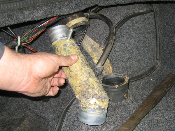 Disconnect the hose clips and pull the cap out. There is also a short stub
for a smaller hose, which I think is a breather connected to the "carbon purge canister" on the S3C - take off that clip and pull off the hose as well.
Disconnect the hose clips and pull the cap out. There is also a short stub
for a smaller hose, which I think is a breather connected to the "carbon purge canister" on the S3C - take off that clip and pull off the hose as well.
I think that's just about it!
I tried putting a jack with some load-spreading blocks of wood under the body in the front passenger footwell, and managed to lift the body about an inch or so, but didn't want to risk cracking it. I also tried the back of the body just in front of the outrigger, but it wasn't for budging and again I didn't want to damage anything. I'm pretty sure there's nothing holding it down though, it just needs more even lifting rather than one corner at a time.
14. There is a cable tie that holds the brake pipe to the top offside chassis member, at the front. I cut it off, to allow the pipe to flex a bit as the body lifts. The clutch pipe has a big bend in it so shouldn't be stressed. Not as much as I am by this stage.
 15. You need to disconnect the wiring to the petrol tank sender. There's also a small earth connection to the end of the top crossrail just in front of the
petrol cap, and that has to be disconnected too. You can see it in this photo just in front of the block of wood between the chassis and the body. I put
one long bit of wood across from side to side, then pack it up between the wood and chassis with thin plywood. There are a couple of rubber pads just at
that point, and I'll need those when I put it down again, so I put them away safe.
15. You need to disconnect the wiring to the petrol tank sender. There's also a small earth connection to the end of the top crossrail just in front of the
petrol cap, and that has to be disconnected too. You can see it in this photo just in front of the block of wood between the chassis and the body. I put
one long bit of wood across from side to side, then pack it up between the wood and chassis with thin plywood. There are a couple of rubber pads just at
that point, and I'll need those when I put it down again, so I put them away safe.
You can also see the cloth stuffed into the neck of the petrol tank to stop any stray sparks dropping in!
16. Before lifting the body, make sure there are no tiny stones wedged between the outer edge of the outrigger and the sill, they can prevent the body lifting. Push a scraper between the tube and the sill, all the way along.
I used two trolley jacks, so that I can lift one end at a time, and not just one corner. I put a jack under the rear edge of the floorpan, on each side of the main chassis. I have a couple of big blocks of wood on top of the jack heads to spread the load so that the fibreglass floor doesn't crack. It lifts easy, a bit at a time on each side. I put a block of wood on each side, between the body and the top of the chassis (just in front of the top of the petrol tank)
Then I lift the front end and pack that up above the inner front body mounting, with little squares of wood and thin plywood. A quick crawl underneath with a light, confirms that nothing is becoming overstretched. There is a cooling hose from the heater that goes down the bulkhead to a pipe under the oil filter, and that looks like the main constraint. We'll see how we get on without draining the cooling system.
Also be aware of the curvature of the metal pipes from the servo to the the front brakes: they will flex a little, but don't lift the body so high that you kink them! Also check the wiring harness at the rear of the nearside wheelarch: it's clipped to the chassis and needs to be released to allow it to rise a little bit as the body is lifted. So far so good!
 Then it's back to the rear, and lift that a little more, then the front again.

 This is about as high as you can get it without disconnecting that coolant pipe at the front offside, or a fuel hose at the rear nearside. Should be high
enough to get around it to repair it though.
This is about as high as you can get it without disconnecting that coolant pipe at the front offside, or a fuel hose at the rear nearside. Should be high
enough to get around it to repair it though.


