:: Install Power Steering ::
:: Why? ::
The TVR S Series is a wonderful wee car, until you come to park it. A combination of limited lock, fat tyres and fat drivers means that getting in
and out of wee spaces can be difficult. Oddly, it seems to get more difficult as the years go by...
Now, this isn't a problem for those of a more ursine build, but for us mere mortals, it can become tricky. To be fair, though, it doesn't really
bother me that much - parking only takes a minute at the end of a journey that van take hours, so power steering is hardly a necessity.
However, I need a wee project to see me through a difficult time of year and give me something else to think about. I also just want to see if I can
do it!
There are two options:
1. Electric power steering column. Some owners have done this using a Vauxhall Corsa C steering column, which has a built-in electric
motor to help you turn the steering. The advantages, as far as I can see from a wee bit of research, are that it's speed adjustable
so you can have full assistance when parking ect, but no assistance at speed; and that it lets you retain the existing rack. The
disadvantage is that you have to cut both steering columns and weld the Vauxhall bit to the TVR (or rather, Ford) bit. That's not
necessarily a deterrent though - but what is a deterrent is that you have to rip the dash out to make up the necessary brackets etc
to support the new column and electric motor.
2. Keep the steering column but install a full hydraulic rack, and an electric pump. This is the route that I chose.
(Disclaimer - the following explains how I fitted a Subaru power steering rack and Vauxhall electric pump to my car. This is purely advisory, and
is given in good faith. Everybody knows that all TVRs are different, so what works on one, might not fit another. This method may work for you,
and it may not. You may need to adapt and improvise. If it goes wrong, then don't blame me!)
:: What You Need ::
The first requirement, obviously, is a steering rack. Based on advice in Chimaera forums, I used a rack from a Subaru Impreza Mk 1
(1992-2000). You need a GC8 variant - the rack is th same length, with the same distance between inner balljoints, and the same mounting points.
They come with different steering ratios from "quick racks" to something like 2.5 turns lock-to-lock. Mine is from a 1998 WX STi.
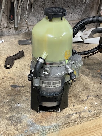
Then you need an electric pump - Citroen Saxo or Vauxhall Astra Mk5 appear to be the pumps of choice for the boys and girls modifying
their Chimaeras and Griffiths. Vauxhall Astra pumps are easier to find (and cheaper) than Citroen Saxo ones. They also apparently give a slightly
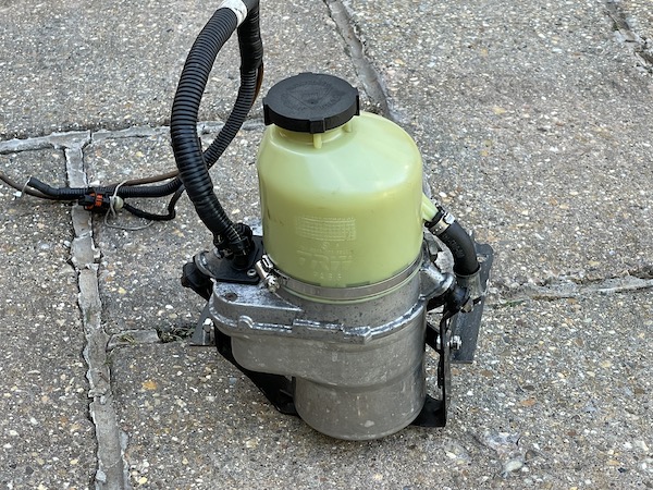
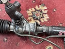
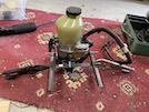
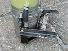
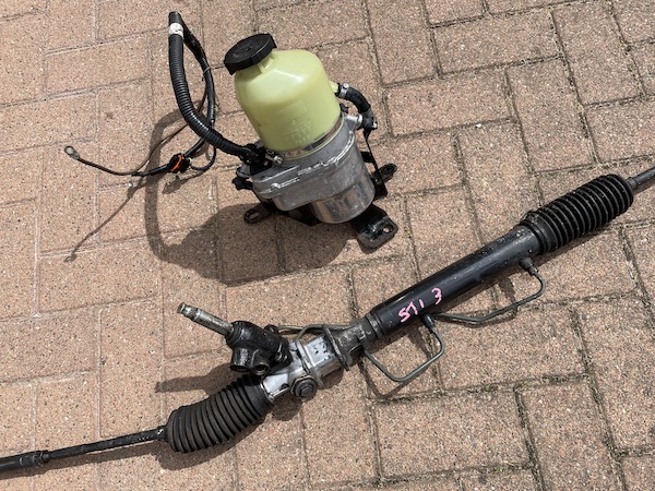
higher pump pressure. The correct pump is an Astra Mk5 TRX pump - I find one complete with hoses, brackets and wiring.
 After a bit of a clean up, they look not too bad!
Those 2 main components are only the start though! You'll also need the following bits and pieces (all will be explained!) :
Rack bushes and mounts
- Subaru racks have two different sizes of mounts - 25mm and 30mm wide, most are 30mm, but check first before you order.
2 No flat plate spacers, 5mm thick, 120mm long by 25 or 30mm wide (depending on the width of the bushes) with 10mm dia holes at 80mm centres.
Bottom Universal Joint from a Ford KA Mk1 -1996-2008 or Fiesta MK3/4 1989-1995.
New or modified steering shaft
20mm long 10mm ID Bolt Spacers
New track rods
New rack gaiters (probably)
Power steering fluid.
Lithium grease.
Various electrical wiring including an in-line 80A fuse holder
and
U-Bolts for the pump bracket
You'll also need some scrap metal to make a bracket for the pump - I bought a metre of angle iron from B&Q.
and various bolts, washers etc.
You'll also need a high pressure hose from the pump to the rack, and a low pressure hose back from the rack to the pump. I ended up making these up
myself, since none of the local hydraulic hose suppliers seemed to be interested.
:: Remove TVR Manual Rack ::
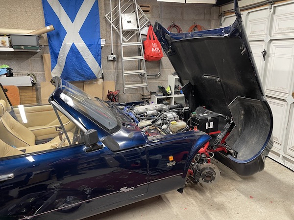
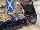 I jack the car up on to axle stands and take off the front wheels and the bonnet stay so that I can open it vertically. Then I take
the battery out so that I can see what I'm doing.
I jack the car up on to axle stands and take off the front wheels and the bonnet stay so that I can open it vertically. Then I take
the battery out so that I can see what I'm doing.
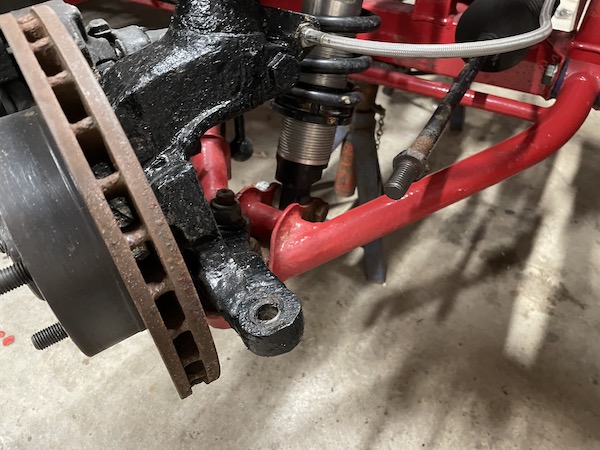
 Loosen the locknut, then the balljoint nut - don't take it off just now though, leave it on to protect the threads while I use a balljoint splitter -
then remove nut and wind off the joint - 12 turns each side. Leave the track rods on the rack, but you'll need those balljoints later!
Loosen the locknut, then the balljoint nut - don't take it off just now though, leave it on to protect the threads while I use a balljoint splitter -
then remove nut and wind off the joint - 12 turns each side. Leave the track rods on the rack, but you'll need those balljoints later!
 I mark the positions of the top and bottom UJs on the steering column shaft, and remove the top UJ then the bottom. That lets me get the steering shaft
out.
I mark the positions of the top and bottom UJs on the steering column shaft, and remove the top UJ then the bottom. That lets me get the steering shaft
out.
Then I remove the 4 mounting bolts to the chassis, and manoeuvre the rack out sideways.
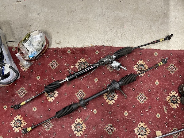
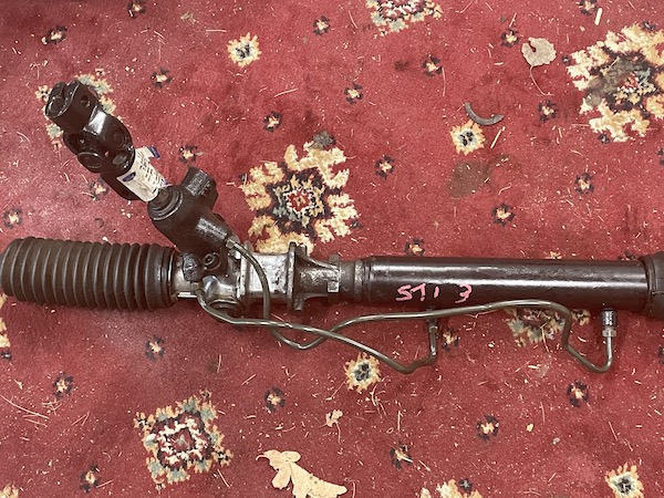
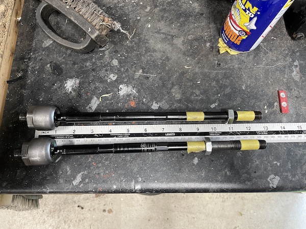
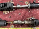
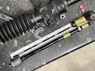
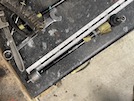
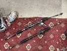 Here's the two steering racks side by side, with the balljoints back on where they were originally. You can see that the rack itself is the same length
but the overall track of the TVR is much shorter.
Here's the two steering racks side by side, with the balljoints back on where they were originally. You can see that the rack itself is the same length
but the overall track of the TVR is much shorter.
:: Prepare the Subaru Rack ::
Don't be thinking that the steering rack is a direct bolt-on replacement - it isn't. You need to do a bit of work on it first.
First off, as far as I could find, there isn't a universal joint that fits the Subaru spline on one end, and the Ford / TVR steering shaft on the
other end. So you need to alter the pinion to fit the Ford Ka UJ.
Next, the Subaru track rod ends have a different taper on them, so they won't go into the hub. SO you need to use the TVR track rod ends.
Unfortunately, those track rod ends have a metric thread, and don't fit the Subaru track rods which have a UNF thread. So you need to change those too.
Finally, the big connectors for the power steering pipes between the pump and the rack would foul on the chassis, so you have to turn the pinion round
by 180 degrees so that the big connectors are on top.
So here's the full lowdown on preparing the rack:
Prepare Pinion
 I undo the fluid pipes from the pinion, and then the two bolts holding the pinion to the rack (they are bloody tight) and extract the pinion.
On mine, there were three spacers or shims just inside the rack - don't lose them!
I undo the fluid pipes from the pinion, and then the two bolts holding the pinion to the rack (they are bloody tight) and extract the pinion.
On mine, there were three spacers or shims just inside the rack - don't lose them!
 Here's the end of the Ford Ka steering joint - it measures 16.8mm across the flats.
Right - time for some sums. I measure the pinion shaft with a vernier - it's 17.9mm diameter at several points along its length.
So, the pinion needs about 1mm filed off on 6 faces - or around .5 mm off each face - to fit that joint. I want it to be as snug as possible
in that joint, so I don't want to accidentally take off too much, so I'm not going to use power tools for this - just a flat hand file and
frequent measurements with a vernier!
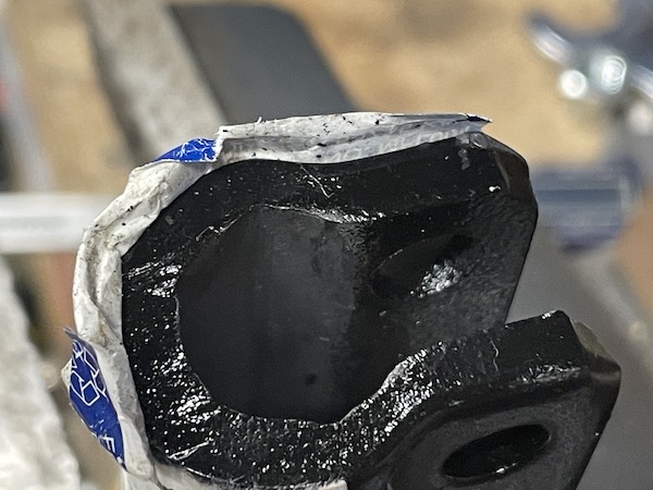
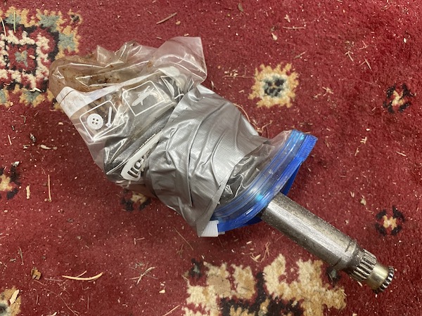
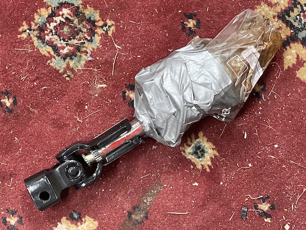
 With the pinion back out, I put it in a plastic freezer bag to keep any metal filings out of the teeth, and tape it up (I did add more tape
around the neck of the bag to seal it better).
With the pinion back out, I put it in a plastic freezer bag to keep any metal filings out of the teeth, and tape it up (I did add more tape
around the neck of the bag to seal it better).
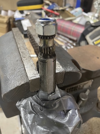
 This is the point of no return. I superglue a 17mm nut to the top of the shaft to act as a filing guide - to show the alignment of the
6 faces. There's a pin that goes through the shaft, and I make sure that's across 2 points so that I won't be filing anything off it.
This is the point of no return. I superglue a 17mm nut to the top of the shaft to act as a filing guide - to show the alignment of the
6 faces. There's a pin that goes through the shaft, and I make sure that's across 2 points so that I won't be filing anything off it.
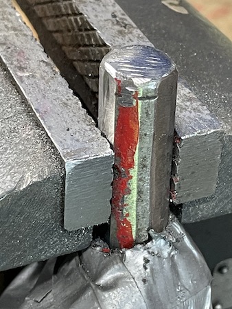
 Then I align the nut with the end of the vice jaws, and start filing with the file straight across the end of the vice, removing the pinion
often to check measurements. I file until the measurement is 17.3mm (half way between 17.9 and 16.8) then turn the shaft round, align the
edge of the nut again, and file until the overall width it 16.8mm.
Then I align the nut with the end of the vice jaws, and start filing with the file straight across the end of the vice, removing the pinion
often to check measurements. I file until the measurement is 17.3mm (half way between 17.9 and 16.8) then turn the shaft round, align the
edge of the nut again, and file until the overall width it 16.8mm.
Then I turn the pinion 60 degrees, again aligning the face of the nut, and file the next 2 faces in the same way. For the last 2 faces, I'm
only going to file one to the hex shape - I'll leave a wee bit more "meat" on the other face to see if I can file a slot for the pinch bolt
later.
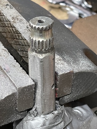
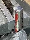
 I keep trying the shaft in the joint, and filing wee bits off the flats, until I have a nice even hex that fits fairly tightly. You can see
in this photo that pin that goes through the shaft - avoiding the flats so I haven't filed anything off it.
I keep trying the shaft in the joint, and filing wee bits off the flats, until I have a nice even hex that fits fairly tightly. You can see
in this photo that pin that goes through the shaft - avoiding the flats so I haven't filed anything off it.
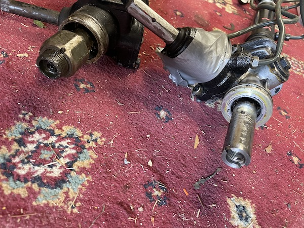
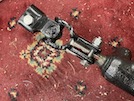
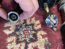
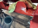
 And here it is, on the famous scabby old red carpet that has featured on this site since the beginning! At the time of this photo, I hadn't
cut the splined end off yet. It's tight though (even without the clamp bolt) with no movement - in fact I struggle to pull it off again!. But
I'm happy with that piece of hand-filed precision engineering!
And here it is, on the famous scabby old red carpet that has featured on this site since the beginning! At the time of this photo, I hadn't
cut the splined end off yet. It's tight though (even without the clamp bolt) with no movement - in fact I struggle to pull it off again!. But
I'm happy with that piece of hand-filed precision engineering!
 Then, I cut the splines off the pinion with an angle grinder. Many sparks ensue.
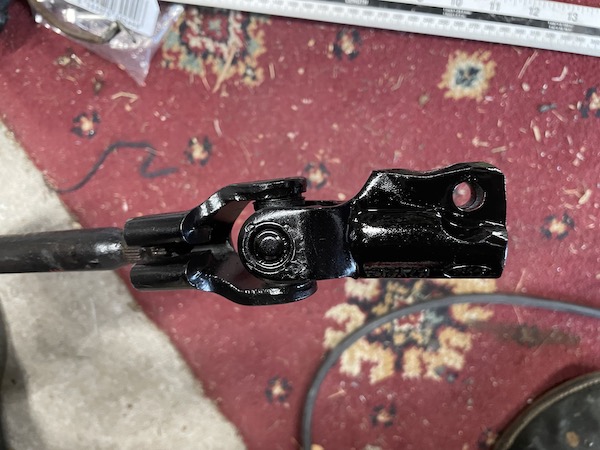
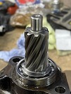
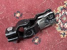
 Then I dig out a couple of clamp bolts, nyloc nuts and spring washers, and fit those loosely for now. Here's the cut-off pinion nicely fitted
to the UJ.
Then I dig out a couple of clamp bolts, nyloc nuts and spring washers, and fit those loosely for now. Here's the cut-off pinion nicely fitted
to the UJ.
Right - now to reassemble the rack...
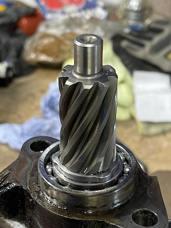
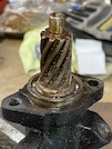 Here's the pinion gear, with the old grease.
 I clean that off with paraffin and a brush, and then re-grease it with new lithium - moly grease.
Then I clean up the inside of the pinion housing (just a bit, no paraffin this time!) and move the rack side-to-side with a screwdriver and
grease the teeth. Then I clean up the three thin shims that I took out of the housing originally, and refit them. Then I refit the housing
"upside down" to where it was before - i.e. with the output connectors (to the rack) on top and the inputs (to and from the pump) underneath.
I put some Loctite on the pinion bolts just to be sure.
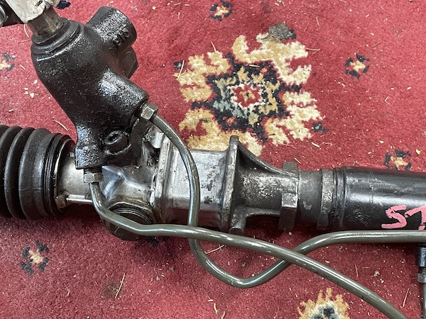
The next step is to re-connect up the pipes on the rack. They have to go back to the same valves that they came out of (don't get this wrong
or the power steering will help you turn left when you turn the wheel to the right, and vice versa, and you don't want that!). It takes a
fair bit of time, bending gradually by hand using a long socket as a bend former, little bits at a time, until the connectors line up.
 No prizes for pipe-bending skills, but it's done.
 I might get new pipes made up and fitted to the rack at some point, but this will do for testing!
Track Rods and Balljoints
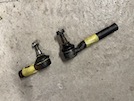 Here's the two balljoints, TVR one on the left and Subaru one on the right.
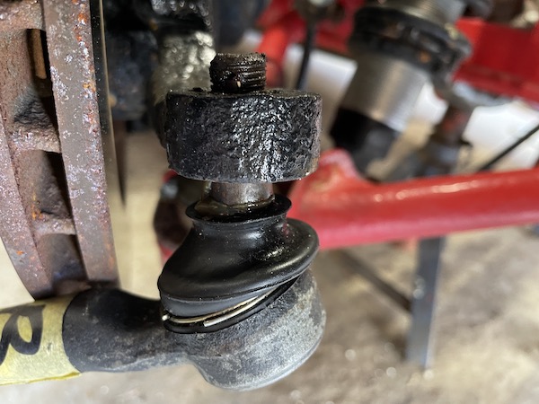
 I found that the Subaru joint does not fit the TVR taper. It barely starts to go in, as you see here.
Second problem is that the TVR joint doesn't fit the Scooby track rod. The TVR joint has a metric thread and the Subaru is UNF.
Next, I check if the TVR steering rods will fit the Subaru rack.
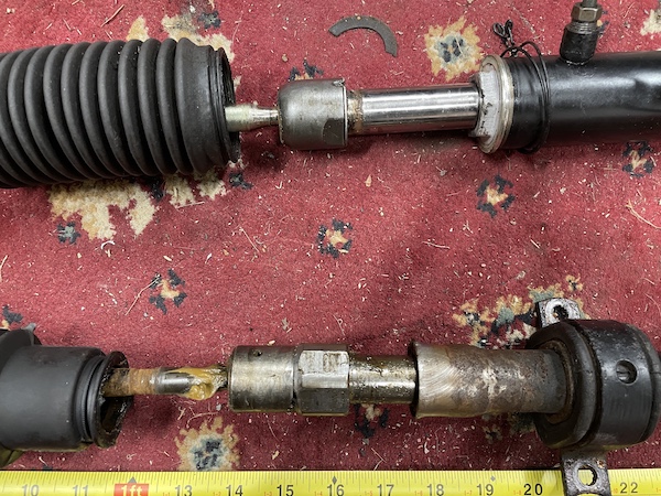
 When I strip back the gaiters it doesn't look hopeful - Subaru joint on top looks totally different from the TVR one below.
 Here's the two joints - TVR on the left has a female thread that screws over the rack end, while the Subaru on the right has a male thread.
 Here's the two rack ends - totally different. So the TVR track rods don't fit the Subaru rack...
This is why I ended up having to buy new track rods, as per the link earlier.
These tie rods come in two lengths, for early and later Chimaeras. The first are 295mm long, the second (most common) are 335mm long. I bought the long ones,
based on advice on the Chimaera forum. Now I know that I should have bought the 295mm ones...
It turns out that shorter track rods are harder to find than the longer ones, and there's no clue of how long they might take to be delivered when they
are ordered. Since the last ones took 3 weeks and were supposedly "in stock", I'm not optimistic. Also, I'll have to pay postage to get new ones delivered,
and postage to send these ones back...
The only difference is the length (and the price, the shorter ones are a fiver more expensive, each), so I may as well modify the ones I have and save time
and money.
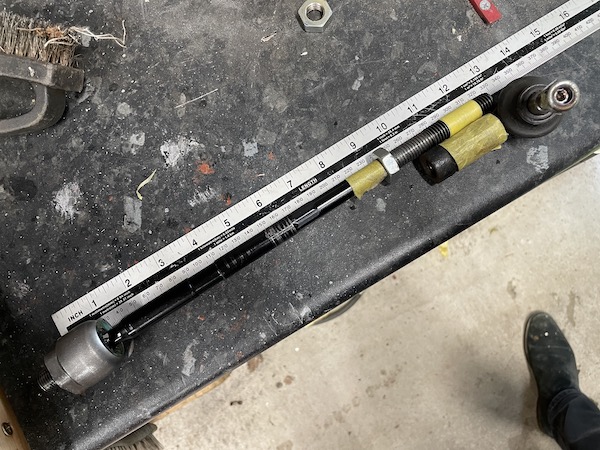
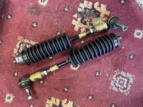
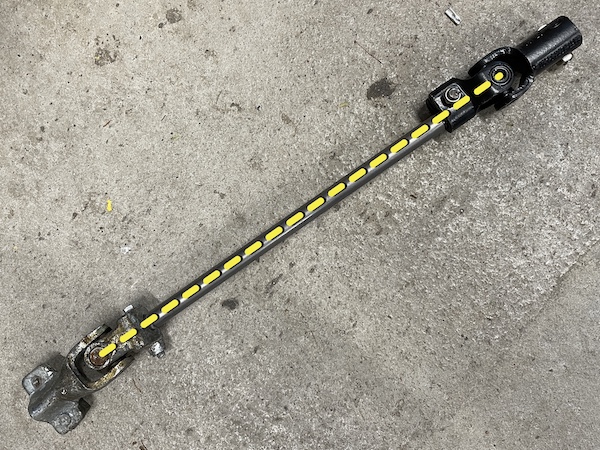
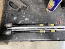
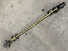
 Here's one of the track rods I have, with the track rod end balljoint at the length it has to be (measured from the total width of the old TVR rack, between
balljoints). The edge of the right-hand bit of yellow tape shows the length the track rod has to be, to give at least an inch of rod inside the thread of the
balljoint. It's an M14 x 2mm thread so that's 12 turns, just the same as on the TVR rack I took off.
Here's one of the track rods I have, with the track rod end balljoint at the length it has to be (measured from the total width of the old TVR rack, between
balljoints). The edge of the right-hand bit of yellow tape shows the length the track rod has to be, to give at least an inch of rod inside the thread of the
balljoint. It's an M14 x 2mm thread so that's 12 turns, just the same as on the TVR rack I took off.
The left-hand bit of tape shows where the threads need to be extended, to allow for the balljoint, the locknut and a bit of scope for adjustment.
So, clamp the track rod in my trusty vice, take the locknut off, cover the inner balljoint to stop metal bits falling into the joint, and spin an M14 die down
the existing thread, then start cutting a new thread, with plent of WD40 to lubricate the cut. Half-turn down, back off a bit, half-turn down back off and so on...
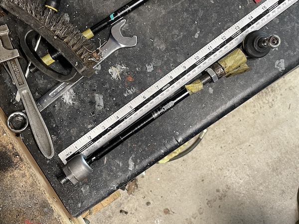
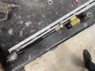
 It takes what seems like ages, but probably really no more than 5 minutes, to thread down to the second bit of tape. Back right off, a wire brush and then clean
the thread with the die again and then the locknut. Here you can see the re-threaded rod, with a bit of tape back on to show where it now needs to be cut.
It takes what seems like ages, but probably really no more than 5 minutes, to thread down to the second bit of tape. Back right off, a wire brush and then clean
the thread with the die again and then the locknut. Here you can see the re-threaded rod, with a bit of tape back on to show where it now needs to be cut.
 and here it is again, beside the balljoint.
 Here it is, threaded and cut, with the balljoint fitted to roughly the right length - plenty of spare thread if needed for on-car adjustments.
Then take it apart again because you forgot to fit the gaiter...
 Then repeat for the other side!
I didn't fit these until the rck was finally in the car - you can't manouevre the rack in and out with the track rods attached.
That's the rack ready for fitting!
:: Make Pump Bracket ::
I had hoped to sit the pump on top of the two chassis members behind the radiator (beside the swirl pot) but I'm a wee bit concerned that might
make routing the hose lines a bit awkward unless I put it at the front - and then bonnet clearance looks awfully close!
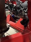
So I decide that I am going to fit it onto the front of the chassis, behind the radiator, and lower it a bit to give bonnet clearance, I hold
the pump in place while I assess its height and how far below chassis level it can sit without risk of it hitting the radiator.
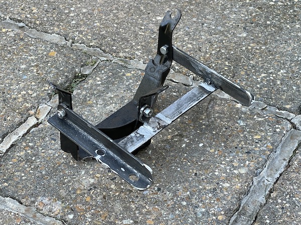
 On the Astra, the pump is mounted in a cradle that is bolted to the body in 3 places. None of those places fit the S, so back home again, I cut
off the 3 mounting arms, ready to make my own.
On the Astra, the pump is mounted in a cradle that is bolted to the body in 3 places. None of those places fit the S, so back home again, I cut
off the 3 mounting arms, ready to make my own.
 This photo shows the pump sitting in the cut-down cradle. I want that to sit with the top of the chassis rail about half-way up the cradle.
So I turn to the home fabricator's friend - angle iron! Unfortunately the next bit was a blur of drills and angle grinders, so I did't take too
many photos. I'll try and explain though.
First I drill a 6mm hole in each leg of the cradle, around 10mm higher than where I want the top of the chassis to be. Then I cut 2 bits of
angle iron to around 200mm long (I'll shorten those later) and drill a 6mm hole in the end of each, and bolt those to the sides of the pump frame.
Those will be the main pump support. The distance between them is 170mm, so I use a couple of wee clamps to hold them temporarily parallel,
and cut another piece of angle iron to around 210mm and clamp that in place at right angles under the sides, around 10mm behind the back of
the frame. That will sit against the top front corner of the chassis rail.
Then I drill another 6mm hole in a leftover piece of iron angle, and then cut it to make a bracket for the back of the cable, and bolt it to
the cradle.
 So now it looks like this. Don't worry about the length of those bolts, those were only temporary.
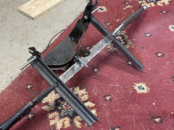
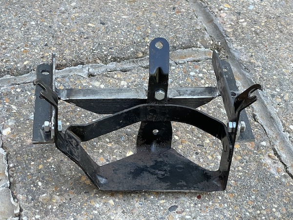
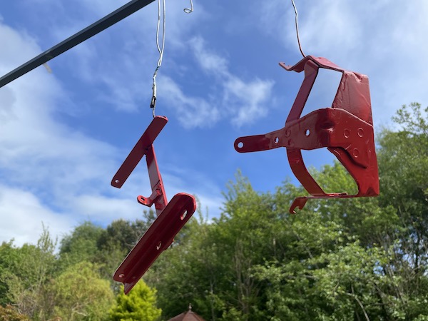
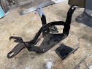
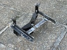
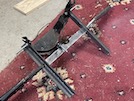 Here's the whole mounting bracket without the pump.
I check that on the car to check that it fits and that it doesn't foul the radiator. It does the first and not the second, so that's perfect!.
So I take the cradle back out and weld it together.
With the bracket welded together, I need to drill holes to clamp it to the chassis. I have a couple of M8 square U-bolts, with 48mm
centre-to-centre (or 40mm between the faces of the 2 arms of the bolt). That should fit snugly to the chassiis which is 38mm square section. So
I mark out the hole centres and drill the holes out - 4mm first then 6 then 8, then eventually 9mm so that the U-bolts will fit through easily.
I also elongate the holes slightly with a hand file to allow for slight adjustment when fitting. Then I cut down the excess behind the mounting
bolts.
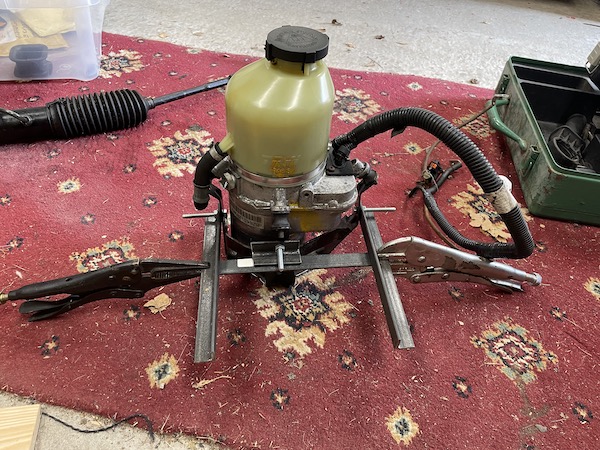
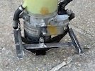
 I refit the Astra pump cradle and it looks like this...
 And this,
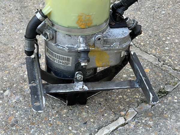
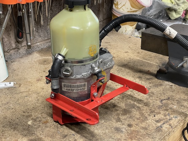
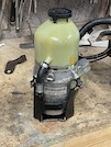
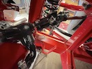
 Here it is with the pump installed in its bracket. This would be looking at the chassis from above the left front wheel, with the pump sitting
in front of the chassis rail.
Here it is with the pump installed in its bracket. This would be looking at the chassis from above the left front wheel, with the pump sitting
in front of the chassis rail.
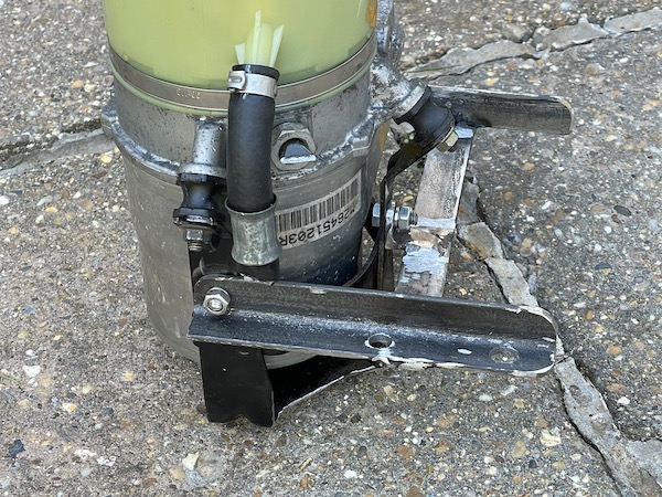
 A closer look from behind...
 and from the front!
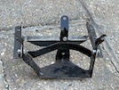
 Then I spray on a couple of coats of paint...
 Happy with that!
When it has dried, I bolt the bracket in place with the U-bolts, and then fit the pump into the bracket.
:: Hoses ::
I had intended to get hydraulic hoses made up, but that didn't go well... There are three local specialists, but they all say that
they only do commercial and contract stuff, not power steering hoses. They say that it's not worth stocking all the bits because
garages buy parts off the shelf for each car.
So I go online and buy a metre of AN6 steel reinforced hose (rated to nearly 3 times the max pressure of the pump) and various re-usable
fittings to attach that between the pump and the rack and back again. At least this way, I can make the hoses to exactly the right
length!
First I need adapters to connect the hose ends into the rack. The JLS Motorsport catalogue includes what they call "bump tube adapters", which
the Chimaera boys say are the right adapters for the Subaru rack - but I can't find them for sale anywhere! The adapters that I have are slightly
different.
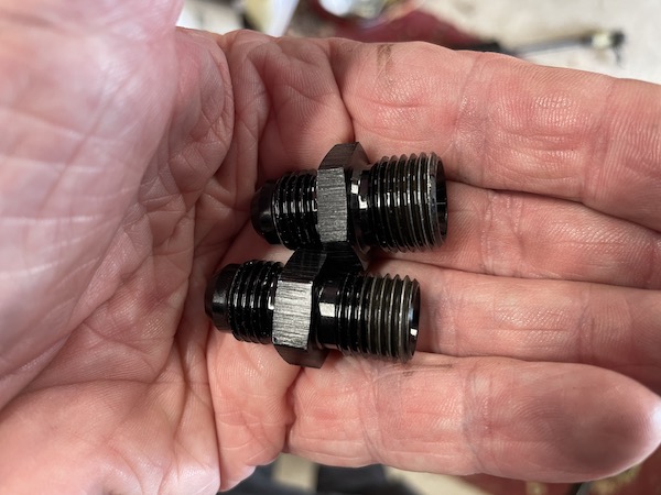
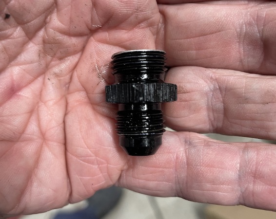
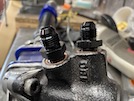
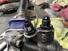
 Here's the 2 adapters I have. The bottom one is an M14 thread and fits the high-pressure inlet to the rack. The top one is M16 thread and is the
low-pressure return to the pump. The hose makers that I visited say that those will be ok, provided that I can get them to seat tightly on their
copper washer seal
Here's the 2 adapters I have. The bottom one is an M14 thread and fits the high-pressure inlet to the rack. The top one is M16 thread and is the
low-pressure return to the pump. The hose makers that I visited say that those will be ok, provided that I can get them to seat tightly on their
copper washer seal
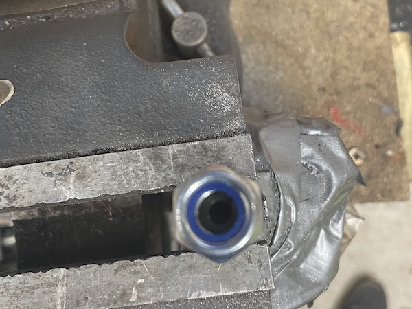
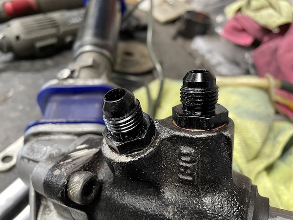
 And here they are fitted to the rack, as far in as they will go. They're a far bit short of sealing the washers!
I measure the 2 gaps with a vernier gauge, and find that I need to cut around 2 threads off the end of each, to get a seal. I cut the ends off with
a wee saw then file them flat.
 here's the return connector with the shortened thread...
 And here they are refitted to the rack, sealing tight against the washers.
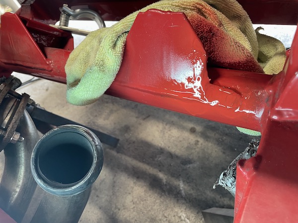
 When I'm happy that the rack bolts down fully but still leaves 1mm of clearance at that connector, I remove the rack for the umpteenth time, and give
the chassis a wee squirt of paint to protect the bare edges.
When I'm happy that the rack bolts down fully but still leaves 1mm of clearance at that connector, I remove the rack for the umpteenth time, and give
the chassis a wee squirt of paint to protect the bare edges.
Then I can make up the feed hose from the pump to the rack. I have bought steel-braided PTFE hose, and re-usable connectors. Unfortunately,
I don't have the technology (or the required number of arms) to make a video or take photos while I'm doing it, but
this YouTube video here shows the whole process.
In summary, though, you wrap the hose in masking tape before you cut it, to prevent fraying of the braiding. I just used a hacksaw. Then take the connector
apart (don't lose the wee olive!) and push the sleeve over the end of the hose. Then spread or flare the metal braising to give a wee bit of clearance between
that and the inner hose lining. Oil the olive and slip it over the lining under the braiding. Make sure the lining sits right inside the olive - push it
against the edge of a vice or workbench. Then oil the fitting and push it into the hose, twisting it in until its against the olive. The push the sleeve back
over, and start the fitting in th thread, then tighten it.
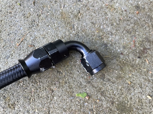
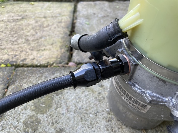
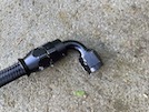 Here's the 90 degree connector for the rack end of the hose.
Then I put the rack in place in the car, and fit that end of the hose. Then I put the pump in place and route the pipe to the pump connector and mark the
length I need. I mark it slightly too long on the basis that it's easy to cut a wee bit off, but a pain in the arse to buy a new hose if it's too short.
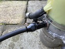 Take the hose back out, repeat the fitting process and here's the straight connector for the pump end of the hose.
The next step is to make the pump return hose. I used 10mm fuel hose with a barb fitting and a clip (it's under low pressure) and fit that to the pinion end.
Then I route the pipe, measure and cut it to length, and fit ir to the pump.
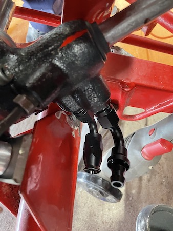
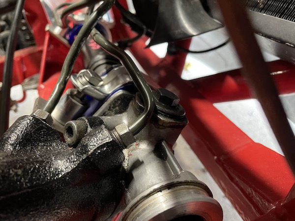
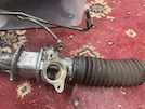
 Here's the completed pump connections...
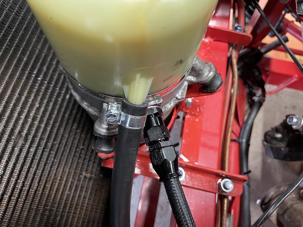
 and here's the connections under the pinion.
:: Fit the Rack ::
When I started to install the rack I quickly realised (well, not that quickly, to be honest) that the edge of the pinion valve housing fouls on
the "web" on the chassis for the steering rack mount. First permanent modification required!
I'm not going to describe here, how many times I tried the rack in place and nibbled a wee bit more off that chassis web. If you want the full
gory details, go to the diary entry for June 22.
 Suffice to say that, once I had ground off enough to get the rack to sit into its right place, that bracing web on the rack mounting partly
covered the steering hose connection - not by much, but it needed more grinding to give clearance.
Suffice to say that, once I had ground off enough to get the rack to sit into its right place, that bracing web on the rack mounting partly
covered the steering hose connection - not by much, but it needed more grinding to give clearance.
So my next step was to trial-fit the hose connectors so that I could see how much more I needed to grind away.
 I then fit the hose connectors so that I can check clearance to the chassis, repeating the routine of fit, remove, grind, fit, remove, grind... As I
grind further down, I realise that it's the weld at the bottom of the web that's now sticking out against the side of the hose connector and just
stopping it all coming together. I don't want that connector to be under any sideways pressure and then breaking, so I need to make sure that there's
even a tiny bit of clearance when it's all in place.
I then fit the hose connectors so that I can check clearance to the chassis, repeating the routine of fit, remove, grind, fit, remove, grind... As I
grind further down, I realise that it's the weld at the bottom of the web that's now sticking out against the side of the hose connector and just
stopping it all coming together. I don't want that connector to be under any sideways pressure and then breaking, so I need to make sure that there's
even a tiny bit of clearance when it's all in place.
 The Dremel is taking forever though, and it's obvious that I'm going to have to grind a fair bit of that web off, to be able to get a connector on,
without breaking it against the chassis when I tighten everything down. So I take off the right-hand exhaust so that I can get the angle grinder in...
The Dremel is taking forever though, and it's obvious that I'm going to have to grind a fair bit of that web off, to be able to get a connector on,
without breaking it against the chassis when I tighten everything down. So I take off the right-hand exhaust so that I can get the angle grinder in...
 This accelerates progress significantly, especially since after around 10 fits and tests, I've ground all of that bit of the web away... That's a
lot of metal removed, but there is still a lot of bracing web left above and below the rack, so I'm sure that it'll all be fine.
This accelerates progress significantly, especially since after around 10 fits and tests, I've ground all of that bit of the web away... That's a
lot of metal removed, but there is still a lot of bracing web left above and below the rack, so I'm sure that it'll all be fine.
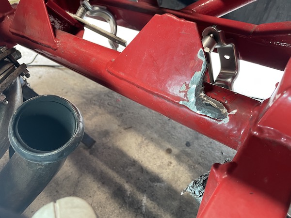
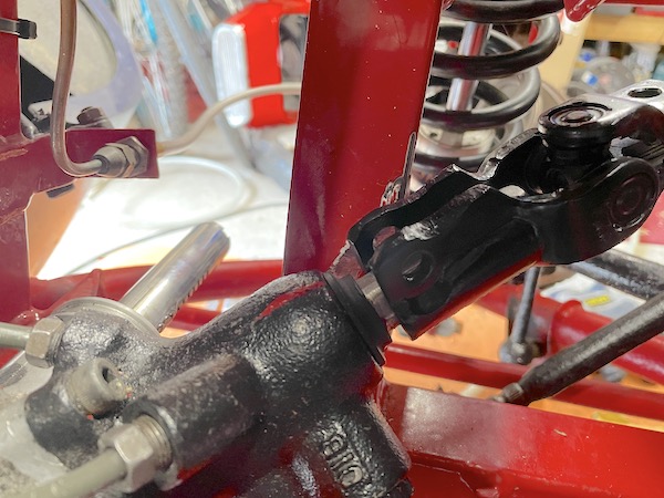
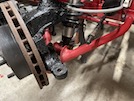
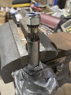
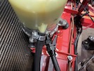
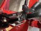
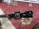
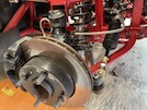
 While the rack is in place, I put the lower UJ onto the pinion to check clearance. There isn't much! The red paint marks in this photo show where the
pinion should be when the steering is straight ahead. I measured that by turning the steering fully one way, and measuring how far the rack
sticks out of the body, then the same on full lock the other way. Set it half-way and that's straight ahead! Ideally, I'd like to get the UJ
further down the shaft though.
While the rack is in place, I put the lower UJ onto the pinion to check clearance. There isn't much! The red paint marks in this photo show where the
pinion should be when the steering is straight ahead. I measured that by turning the steering fully one way, and measuring how far the rack
sticks out of the body, then the same on full lock the other way. Set it half-way and that's straight ahead! Ideally, I'd like to get the UJ
further down the shaft though.
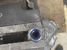
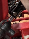
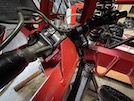
 This photo shows that the vertical angle of the pinion is slightly different from the TVR rack, so I had to extend that customised chassis clearance channel
(the big dent) upwards by a bit. "Percussive adjustment" the F1 teams call it.
This photo shows that the vertical angle of the pinion is slightly different from the TVR rack, so I had to extend that customised chassis clearance channel
(the big dent) upwards by a bit. "Percussive adjustment" the F1 teams call it.
That means "battering it repeatedly with the biggest hammer that I
can lift and swing in the space available." It doesn't need much, just a few mm, but it still takes many whacks to open up the gap even a little.
The UJ clamp is still slightly catching on the front corner, so I grind a teeny bit off it.
 I mark where the UJ is catching on the chassis if I push it right onto the pinion. In my brain, this offers three advantages:
it means that I don't grind away metal right beside the clamp bolt;
The UJ is less likely to come off if the clamp bolt does come loose; and
it maximises the distance between the UJ and the bottom of the steering column so I might not have to shorten the new steering shaft.
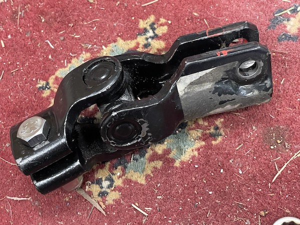
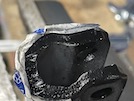
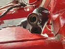
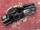
 Here's the UJ after it has been ground down to clear the chassis.
 I shorten the clamp bolt so that it only just goes through the nut, but the nut is still only just clearing the chassis, so I use a flat file to take a wee
bit of the faces off the clamp and the base of the nut. Now it's perfect!
I shorten the clamp bolt so that it only just goes through the nut, but the nut is still only just clearing the chassis, so I use a flat file to take a wee
bit of the faces off the clamp and the base of the nut. Now it's perfect!
 Then I give the UJ a wee spray of paint just to tidy it up and protect the bare metal.
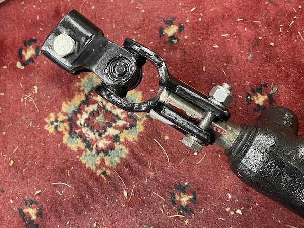
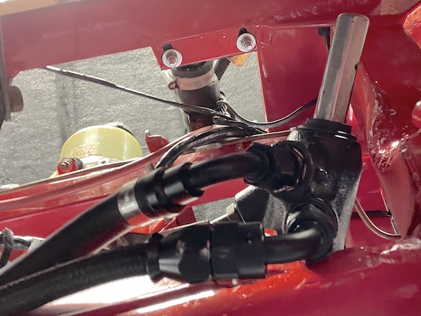
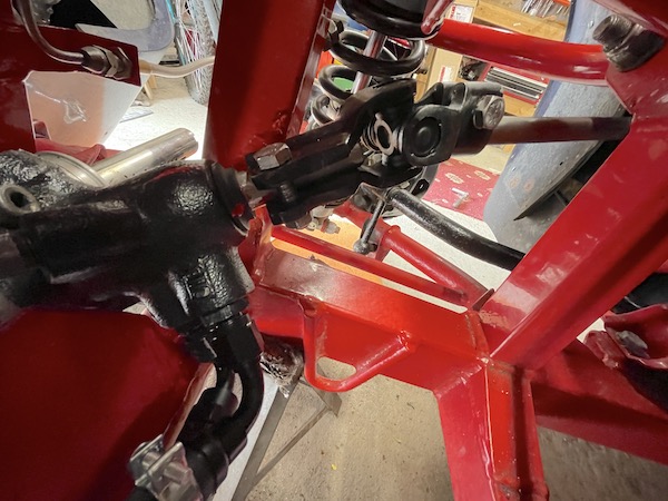
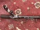
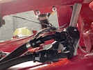
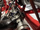
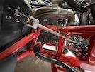
 Here's the rack, the feed hose and the UJ all in place.
 And here's the UJ on the pinion, as far on as it will go.
When I'm happy that the rack bolts down fully but still leaves 1mm of clearance at that hose connector and at the pinion clamp bolt, I take it all out
(again! and give it a wee squirt of paint to protect the bare edges.
The final fitting!
 First set up the rack mounting clamps. Here you can see the flat 5mm thick spacer that lifts the rack slightly and also fits better into the mounting rubbers.
You can also see the mounting bolts and the 20mm thick tube spacers. I realised during the fettling that I needed the spacer slightly thicker, so there's also
a 1.5mm flat washer in there.
First set up the rack mounting clamps. Here you can see the flat 5mm thick spacer that lifts the rack slightly and also fits better into the mounting rubbers.
You can also see the mounting bolts and the 20mm thick tube spacers. I realised during the fettling that I needed the spacer slightly thicker, so there's also
a 1.5mm flat washer in there.
The standard racks fits in from the side, but the Subaru rack doesn't, because the pinion is muc=h longer and also the fixed pipes get in the way. The rack goes
in from the top, upside down, tucking the nearside through the chassis and then rotating it as you lower, into its position.
Before clamping the rack down, I fit the feed hose to the pinion, and tighten it into position - this is a lot easier when it's upside down and not hard
against the chassis!
 Here you can see the spacer and washer before tightening down.
Then refit the pump to its bracket and reconnect all the hoses.
 Finally, fit the track rods to the rack - a bit of loctite on the thread and screw them into the rack ends. Then fit the tapers into the hubs and the job's done!
:: Steering Column Shaft ::
Since the Subaru pinion and the Ford UJ is much longer then the original one, the shaft connectin to the steering column needs to be shorter. With the
rack in place, I put the top UJ onto the bottom of the steering column and measure how long the steering shaft needs to be.
Around 310mm with the bottom UJ where it is, maybe 320mm if I can get enough chassis clearance to get that UJ further down the pinion. I
order a 330mm shaft, and I hope that will still fit if I grind a wee bit off each end. If not, I can shorten it in the middle and weld a
tubed joint.
The existing TVR steering shaft is 380mm, so I could just shorten that, but then I wouldn't be able to go back and re-install the TVR rack for
our run in July, if I had to.
 To fit it, first I remove the top UJ from the old shaft, and the new bottom UJ from the pinion. I line up the clamps so that the UJs are "in phase" - that means that
the yokes on each end of the shaft are in line and not at angles, which makes the steering feel notchy.
To fit it, first I remove the top UJ from the old shaft, and the new bottom UJ from the pinion. I line up the clamps so that the UJs are "in phase" - that means that
the yokes on each end of the shaft are in line and not at angles, which makes the steering feel notchy.
 I set the rack to the straight-ahead position and fit the bottom UJ to the pinion.
 Then I set the steering wheel straight ahead and fit the top UJ to the bottom of the column.
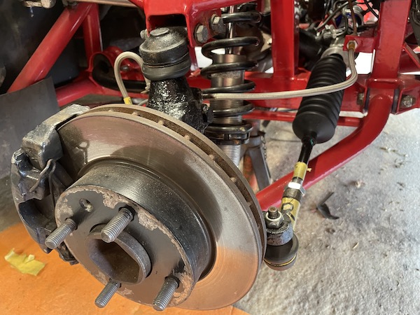
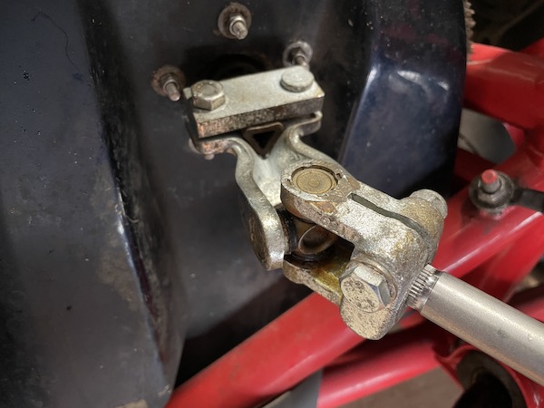
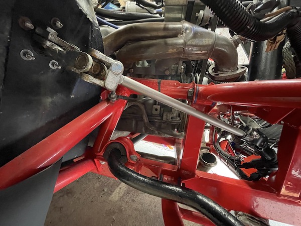
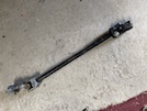
 and here's the completed shaft installation - the 320mm length fits perfectly!
:: Electrical Wiring ::
The first step on the wiring is to remove all of the existing corrugated tubing to expose the bare wires. Then I route the main live straight to the battery,
via a big inline fuse holder. Then I route the main earth to a chassis earth point just under the coolant swirl point.
That leaves me with 2 wires to extend and connect - one to an ignition switched source, through another 10A fuse, and one to the alternator warning light terminal.
I open up all of the black plastic conduit on the car, and feed in a black wire from the ignition coil, and a green wire from the back of the alternator.
Then I use a mass of cable ties to fix all of this wiring back into position.
I need another in-line fuse for the ignition trigger wire though, so I'll need to buy one.
With that done, I re-installed the battery, inserted the fuses (80A in the main battery feed, 10A in the ignition feed) and fired it up!
It's designed so that the pump doesn't start until the ignition light goes out. I check that it does, but ony for a few seconds because I haven't filled the
system with fluid yet.
So far so good! So next I fill the reservoir with fluid, start it again and get the pump running, and turn the steering from lock to lock to bleed the fluid
through the system. Then I top up the system and check each pipe, hose and connector for leaks.
So far so good again!
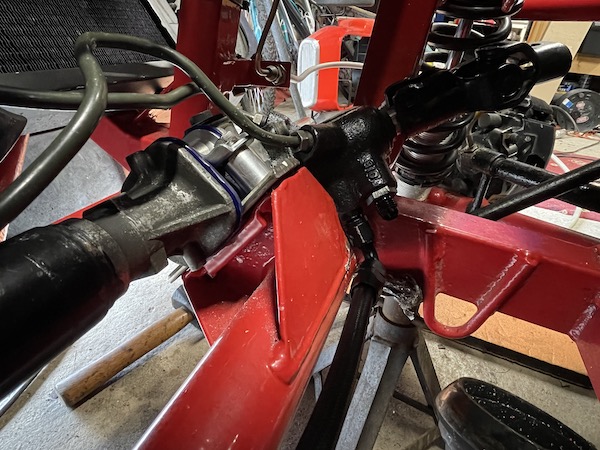
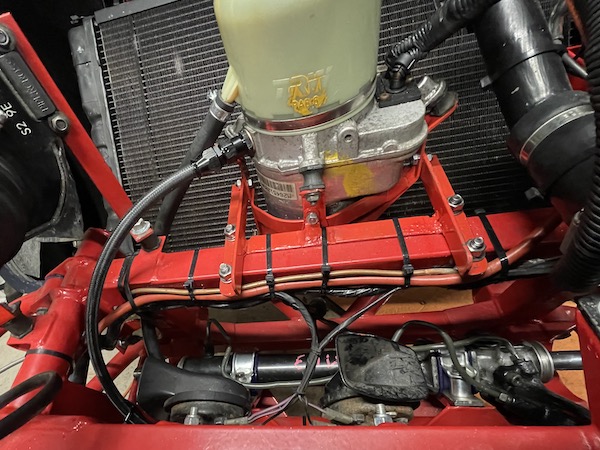
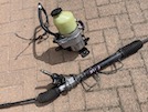
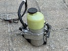
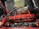 Here's the installed system.
:: Check / Adjust Geometry & Lock ::
The last steps are to check the front wheel alignment and then that the tyres don't foul on the body on full lock.
So with the wheels back on, I roll the car forward and back a bit to centralise the steering and settle the suspension, then check that the steering wheel is
more or less straight. Then I set up string lines using axle stands, just touching the front and rear tyres. That shows that I have slightly too much toe-in.
Then I can lift the bonnet and tweak the tie rods out of the track rod ends slightly, until the wheels are parallel. Then tweak them in again by 1/2 a turn each
side and tighten the lock nut.
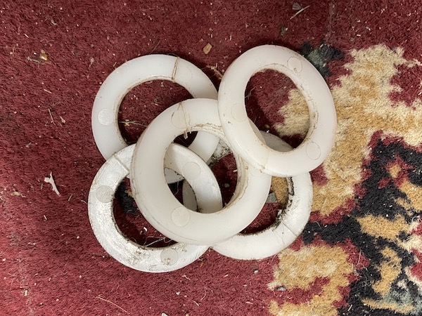
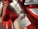
 I have made up some plastic spacers that will fit as rack stops so that the tyres don't rub on the chassis or inner wings.
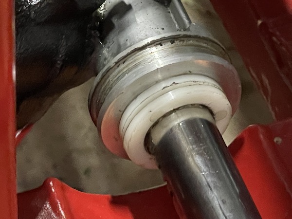
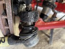
 Those fit between the rack body and the inner balljoint, like this.
I check the wheels on full lock in ach direction, to make sure that the tyres don't rub on the inner wings. I need 2 plastic washers each side, to slightly
limit rack travel.
A short road test shows that it's feckin' brilliant! So I go back home and pull the gaiters onto the rack body and secure them with plastic ties.
So there we are - not exactly a bolt-on job, this has been a trial of grinding, filing, hammering, sawing, welding, about 50 trial fits for measuring, and various
frustrations along the way. However, I wanted to see if I could do it, and I have!
 After a bit of a clean up, they look not too bad!