As most TVR owners will know, although the chassis, bodywork and major suspension components were TVR built, most of the mechanical components, certainly on TVRs built up to the mid 1990s, were sourced from various manufacturer's parts bins - none more so than the braking system!
The S Series has Ford Sierra hubs, brake disks, drums, shoes and calipers at the "wheel end" of the braking system. The only change (as far as I am aware) was a change from drum rear brakes to disks, for the S4C and V8S.
At the "pedal end", though, there was another important change. The early S Series were fitted with a Ford Fiesta brake servo, operating a Saab brake master cylinder. The master cylinder had a remote brake fluid reservoir fixed to the bulkhead, connected to the cylinder by two rubber tubes running above the right hand exhaust. Those tubes had to be heat shielded, in case they perished (and then you suddenly run out of brake fluid, which is never a good idea).
As far as I have been able to ascertain, the Saab master cylinder and reservoir are no longer available, so if yours fails, you really have no choice but to upgrade to the later system.
Later models had a Ford Fiesta master cylinder on the same servo (both Fiesta Mk 3) with an integral brake fluid reservoir. The servo was turned through 90 degrees though, for reasons we'll come to in a minute.
Unfortunately, the position of the servo in either case, means that the underside gets covered in crud, and starts to rust through. In extreme cases, this can lead to perforation of the servo diaphragm, or, even worse, the servo coming apart when you brake,. Again, neither of these are ideal scenarios.
So when I found a bit of rust on the seam under the servo, I decided to change it, and to upgrade to the later brake system while I was at it. And this is how I did it.
The master cylinder and servo part numbers are explained on this thread on Pistonheads, and I can guarantee that those parts fit, as I have set out below. The Master cylinders are fairly easy to obtain through ebay etc, but the servos are getting difficult to find. Ford discontinued the servo just as I was looking for one (October 2011) and supplies to TVR specialists were also getting short. I think I managed to buy the last one in stock - future supplies might be more expensive. Since the same servo is fitted to the Griffith, Chimaera and Cerbera, though, I suspect that the TVR suppliers will have to come up with some alternative.
Once again, the standard disclaimer. The following explains how I did this job on my car, and is given as helpful guidance only. You are welcome to follow this advice, but you do so at your own risk - vehicle brake systems are obviously extremely important, so if you follow this advice, but your brakes subsequently go wrong, don't come running to blame me after you have extracted your face out of the arse of the bus you were following at the time.
So, with that out of the way, let's get to the guide.
First step, as always, is to get the car up off the ground and take the wheels off. It's not strictly necessary for the whole job, but you will need to bleed all the brakes at the end, and taking the wheels off now will prevent any absent minded nitwit (ahem...) jumping in and trying to move it before remembering that it's got no brakes. If you do this, see advice above, but substitute "garage wall" for "arse of bus".
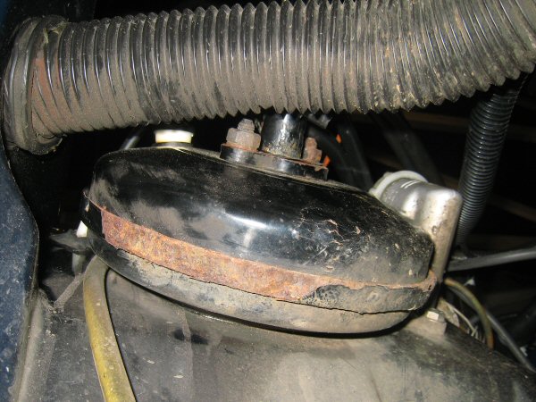 Then I remove the front offside wheel arch. Once the wheelarch is off, I have a look at the underside of the servo - it looks like surface rust in this
photo, but it's flaking off in chunks.
Then I remove the front offside wheel arch. Once the wheelarch is off, I have a look at the underside of the servo - it looks like surface rust in this
photo, but it's flaking off in chunks.
 Here's the servo and master cylinder from above. Looks ok eh?
Now at this stage, I would advise you to disconnect the steering column - it might not be strictly necessary, but I think its removal improves accessibility to the pedal and bulkhead bolts, so I did. I cut off the cable tie and pull back the gaiter I installed, then loosen the pinch bolt and disconnect the steering joint. Then inside the car, I remove the steering cowl, disconnect the wiring to the lights and indicator and wiper switches, and the dreaded ignition block connector, then remove the two 17mm bolts that hold the column up under the dash and remove the column from the car.
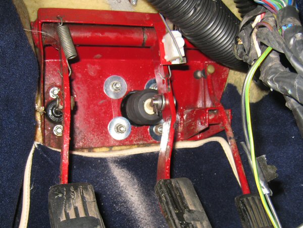
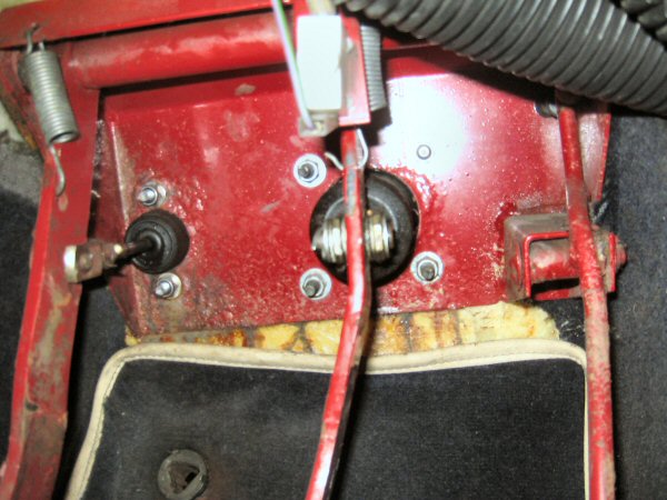 Here's the brake servo bolts inside the car. You can see from this that the bolts aren't in a square, two of them (the ones at 10 o'clock and 4 o'clock
in the photo) are closer to the centre than the other two. This design feature is intended to prevent spanner-monkeys fitting the servo in its side so
that the master cyinder is then also sideways, and all the brake fluid falls out. Unfortunately, Saab (who made this ,aster cylinder) and Ford (who made
the master cylinder I will be fitting) didn't adopt a universal approach on what way was "sideways" so I will have to re-drill those holes when I come to
fit the new servo.
Here's the brake servo bolts inside the car. You can see from this that the bolts aren't in a square, two of them (the ones at 10 o'clock and 4 o'clock
in the photo) are closer to the centre than the other two. This design feature is intended to prevent spanner-monkeys fitting the servo in its side so
that the master cyinder is then also sideways, and all the brake fluid falls out. Unfortunately, Saab (who made this ,aster cylinder) and Ford (who made
the master cylinder I will be fitting) didn't adopt a universal approach on what way was "sideways" so I will have to re-drill those holes when I come to
fit the new servo.
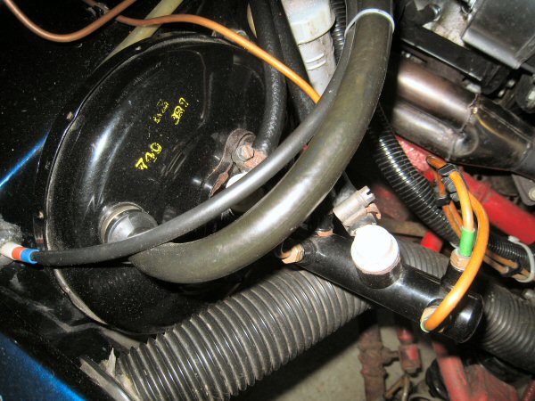
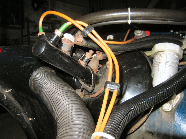
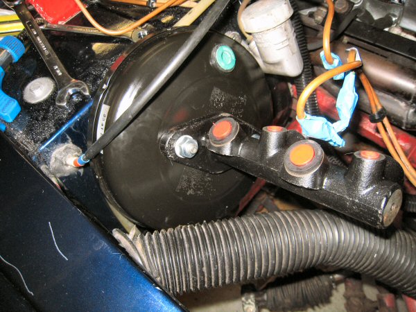
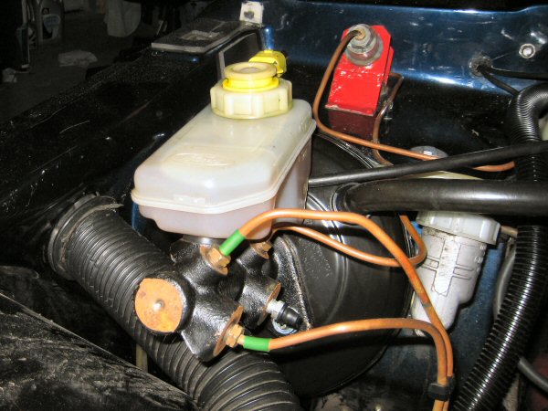
 This shows the Saab arrangement with the remote reservoir connected by two pipes.
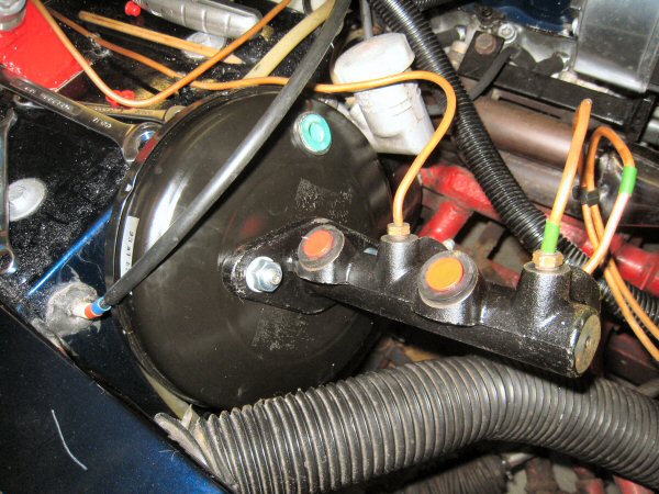
 This is from the other side, and shows the state of the master cylinder.
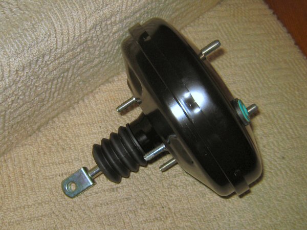 This is a brand new straight-out-of-the-box Fiesta Mk3 brake servo, as discontinued by Ford 2 weeks previously. I also bought a second hand plastic
reservoir (the advert for the master cylinder said that one was included, but it wasn't).
This is a brand new straight-out-of-the-box Fiesta Mk3 brake servo, as discontinued by Ford 2 weeks previously. I also bought a second hand plastic
reservoir (the advert for the master cylinder said that one was included, but it wasn't).
So at last it's on to replacing the master cylinder. First I use a vacuum pump to remove the brake fluid from the reservoir. Once that's empty, I open both front brake nipples and one of the rear ones, and drain some fluid down to empty the master cylinder and pipes as much as I can.
Then it's into the footwell to remove the split pin and push out the clevis pin from the brake pedal.
The next step is to remove the vacuum hose from the servo (it just pulls out) and then the two rubber hoses connecting the reservoir to the master cylinder. They are held on with jubilee clips so that doesn't take long. Then I disconnect the three metal brake pipes from the master cylinder, and move them carefully aside, after putting some tape around the ends to keep dust and crud out. The master cylinder unbolts from the servo and after I've made sure it's empty, I set it aside.
Then I use a long extension bar and 13mm socket to remove the 4 nuts in the footwell, holding the servo to the bulkhead. That lets me jiggle the servo free and off the car.
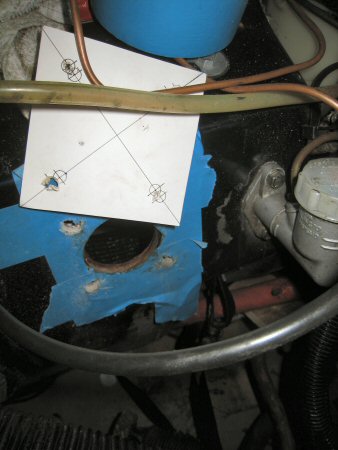
The two servos look identical, although the master cylinders aren't - the new one's mounting holes are 90 degrees out from the old one, so the servo has to be turned by that amount. The mounting bolts to the bulkhead are offset though - two are further from the centre than the other two. To turn the servo, then, you have to re-drill the bulkhead according to this template, courtesy of Richard Jarvis:
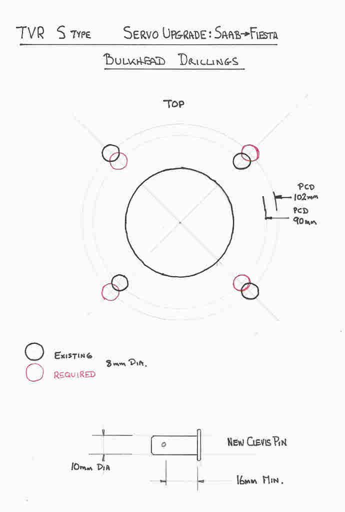
Two diametrically opposite holes have to go CLOSER, from 102mm apart, to 90mm apart. The other two diametrically opposite holes have to go OUT from 90mm to 102 mmm. Now you'll see there that all the holes are supposed to be 8mmm diameter, and that the offset between the old hole and the new one is 6mm - that means that the centre of the new hole is only 2mm from the edge of the old hole. My problem, though, is that the existing holes seem to all be 10mm dia, so the new hole centre is right on the edge of the old one - so there's no way of getting a drill to stay in place and drill down the new centre.
What I need to do, is file the two inner holes outwards by 6mm, and the two outer holes inwards by the same amount, to make oval holes, and then bolt the servo in with plenty sealant and big washers on the inside to clamp it against the metal pedal box.
 I have one more part to remove, the old brake fluid reservoir. It's held on with two wee brackets bolted through the bulkhead on to inaccessible nuts above
the steering column. You might need the help of a glamorous assistant, to hold a spanner on them AND turn the bolt on the outside at the same time. but I
manage to brace a spanner on each nut, and remove the bolts, and the reservoir comes free. That's a very short sentence for something that took bleeding ages,
nipping the nut a little bit at a time. At least there was no impressionable assistant to be corrupted by bad words.
I have one more part to remove, the old brake fluid reservoir. It's held on with two wee brackets bolted through the bulkhead on to inaccessible nuts above
the steering column. You might need the help of a glamorous assistant, to hold a spanner on them AND turn the bolt on the outside at the same time. but I
manage to brace a spanner on each nut, and remove the bolts, and the reservoir comes free. That's a very short sentence for something that took bleeding ages,
nipping the nut a little bit at a time. At least there was no impressionable assistant to be corrupted by bad words.
 So the next step is to re-drill the bulkhead. First I stick masking tape over the existing holes in the bulkhead, to give me something to mark on. Then I
take the template I made, and mark through the edges of the enlarged holes - two to be elongated outwards, the other two inwards.
So the next step is to re-drill the bulkhead. First I stick masking tape over the existing holes in the bulkhead, to give me something to mark on. Then I
take the template I made, and mark through the edges of the enlarged holes - two to be elongated outwards, the other two inwards.
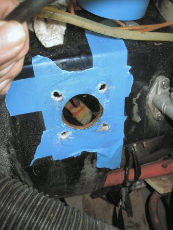 Then using a grinding burr in a Dremel, I grind back the fibreglass to the marks I made - that's easy. Then the difficult bit is grinding back the metal of
the pedal box, to the same shape. I do a few trial fits of the old servo, turned through 90 degrees, and gradually grind and file the metal back until the
servo slips into place. While I'm doing that, incidentally, I notice that there's brake fluid dripping out of the old servo - the master cylinder has
obviously started leaking, so I'm changing it none too soon!
Then using a grinding burr in a Dremel, I grind back the fibreglass to the marks I made - that's easy. Then the difficult bit is grinding back the metal of
the pedal box, to the same shape. I do a few trial fits of the old servo, turned through 90 degrees, and gradually grind and file the metal back until the
servo slips into place. While I'm doing that, incidentally, I notice that there's brake fluid dripping out of the old servo - the master cylinder has
obviously started leaking, so I'm changing it none too soon!
 Then I remove the masking tape, and clean off the old sealant that was between the servo and the bulkhead, and also various other bits of sealer
etc on the bulkhead.
Then I remove the masking tape, and clean off the old sealant that was between the servo and the bulkhead, and also various other bits of sealer
etc on the bulkhead.
Then I need to drill a bigger hole in the brake pedal. The old servo had an 8mm clevis pin, but the new one has a 10mm pin. Access is restricted so I bought a right-angle drill adapter, which turned out to be a waste of money, so I ended up hiring a proper right-angle drill for a tenner for a day. Even then, the clutch pedal is in the way... so I find a bit of wood the right thickness and lift the brake pedal back, and brace it on the wood. Then (and here's the enginuity, although I say so myself) I feed a trusty webbing strap through the centre of the steering column bearing, round the clutch pedal and then back through the bearing. Then a knot in the strap, a tyre lever through the loop, braced against another bit of wood against the chassis, holds the clutch pedal down out of the way.
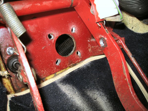 So that gets me to here.
 At last, we're on to assembly! I put the servo in place on the bulkhead, and make sure the clevis pin hole all lines up, and that the washers and nuts fit
without fouling the operation of the servo. THen I remove the servo again and spread sosme silicone sealer around the face that meets the bulkhead, and
bolt it into place.
At last, we're on to assembly! I put the servo in place on the bulkhead, and make sure the clevis pin hole all lines up, and that the washers and nuts fit
without fouling the operation of the servo. THen I remove the servo again and spread sosme silicone sealer around the face that meets the bulkhead, and
bolt it into place.
 Then I insert the clevis pin, with a selection of thick and thin packing washers, to connect the pedal to the servo.
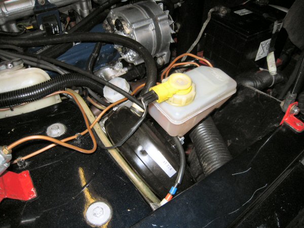
 So now it's time to install the brake master cylinder. This is an easy bit! It just slides on to the two bolts on the servo, and then two washers and nuts
to tighten it in place. You can see in this photo, the bigger top holes that the reservoir fits into, and the smaller ports for the brake pipe connections.
You can also see that the ends of the front brake pipes will have to be re-shaped to fit the alignment of the ports in the new master cylinder, which are
about 45 degrees further round than the old ports were.
So now it's time to install the brake master cylinder. This is an easy bit! It just slides on to the two bolts on the servo, and then two washers and nuts
to tighten it in place. You can see in this photo, the bigger top holes that the reservoir fits into, and the smaller ports for the brake pipe connections.
You can also see that the ends of the front brake pipes will have to be re-shaped to fit the alignment of the ports in the new master cylinder, which are
about 45 degrees further round than the old ports were.
 So - the next step is to connect up those brake pipes! The old brake pipes are copper rather than steel so they bend to shape easily - but I don't know
how long they have been on the car (9 years at least!) so they might be work-hardened, so I am wary of splitting or stretching them. The rear one is
relatively easy - a slight straightening of the end, and it connects straight up. The front ones aren't so easy to align to get the threads to engage, but
they connect eventually.
So - the next step is to connect up those brake pipes! The old brake pipes are copper rather than steel so they bend to shape easily - but I don't know
how long they have been on the car (9 years at least!) so they might be work-hardened, so I am wary of splitting or stretching them. The rear one is
relatively easy - a slight straightening of the end, and it connects straight up. The front ones aren't so easy to align to get the threads to engage, but
they connect eventually.
Then the reservoir pops into the two top ports. Last step is to realign the servo vacuum hose, and cut about 4 inches off the end (that's about 100 mm for those of you who aren't pre-decimal like me) and replace the non-return valve.
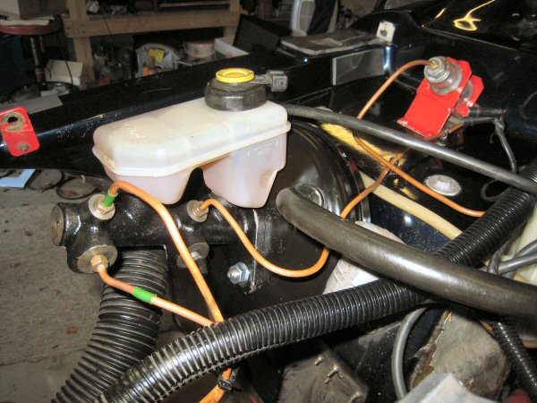 The cylinder has 4 ports but I only need 3, so I put a brake bleed nipple in the spare port (the bottom rear one here) and fill the reservoir.
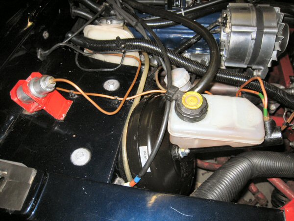 It's a much tidier looking arrangement than the original, and now there's no risk of a rusty servo splitting, or of the rubber pipes to the reservoir
hardening and splitting in the heat from the exhaust (which is not unknown!). That's why they are wrapped in heat-resistant foil!
It's a much tidier looking arrangement than the original, and now there's no risk of a rusty servo splitting, or of the rubber pipes to the reservoir
hardening and splitting in the heat from the exhaust (which is not unknown!). That's why they are wrapped in heat-resistant foil!
I replace the old reservoir mounting bolts, again with a bit of silicone on, to seal the holes in the bulkhead. Again, this is really fiddly and you'll probably need an assistant. I think it would be even more fiddly with the steering column still in place!
After I've given the carpet a vacuum to remove the debris from drilling the bulkhead, I start to fit the steering column. First the column goes through the bulkhead bearing, then I support the steering wheel on a wee box while I carefully route the wiring back to the right connectors - two on the right side for the lights and wipers, to on the left for the indicators and headlight flash etc. Another connector underneath connects up the ignition switch, and then finally there's a single wire to be connected up. There's another connector for the boot switch, and a wire to the manual radiator fan over-ride, but I can't connect those yet.
Right - now to push the steering wheel up into position, and bolt it to the bracket using the two big spacers, being careful not to trap any wiring between the bits.
Then I connect up the radiator and boot release wiring to the switches on the lower steering cowl, and refit that to the column.
Under the bonnet now, to connect up the steering up to the bottom of the column. I had marked which way the UJ went on, and I haven't turned either the steering wheel or the front hubs since, so it goes back exactly as it camne off anyway. Tighten up the pinch bolt and then refit the gaiter I fitted to keep the UJ free of water and grit from the front wheels.
All that remains now, is bleeding the brakes. I've got one of those pressure bleeding kits, but I have never got on with it, and I am also always wary that pressurising the master cylinder from the reservoir could blow the cylinder seals inside out (and that means a full strip and re-seal). That's never happened to me but I've heard to happen to two others. I've also got a one-way valve but I think it's along at the farm. I like to see what I am doing when bleeding brakes, anyway, so I need a pedal-pushing helper for that.
I bought new bleed nipples for the rear wheels (the front ones are ok) so I replace them first, then I bleed all the brakes through, starting with the furthest from the cylinder (ie nearside rear) then working back to finish with the offside front, topping up the reservoir before doing each wheel. When I have finished, I get my wee helper to stomp on the pedal while I go around checking all the connections for any signs of seepage.
 The last step is to wire up the brake fluid warning system to the reservoir cap. I can either transfer the Saab cap over so that I can use the same electrical
connector for the "low fluid warning" system (although my connector keeps falling off), or I can fit the Ford cap to the Ford reservoir - unfortunately, that
means that I need a Ford loom connector, which I don't have, so I would have to get the connector first.
new or from a scrappy.
The last step is to wire up the brake fluid warning system to the reservoir cap. I can either transfer the Saab cap over so that I can use the same electrical
connector for the "low fluid warning" system (although my connector keeps falling off), or I can fit the Ford cap to the Ford reservoir - unfortunately, that
means that I need a Ford loom connector, which I don't have, so I would have to get the connector first.
new or from a scrappy.
I'll have to extend the wiring to the new relocated reservoir anyway, so I decide I'll go with the Saab cap and connectors for now. I start by cutting off the connector wiring (at the loom end) and then solder in two longer bits of wire, with heatshrink over the joints, then tape the two wires together from the loom to the reservoir.
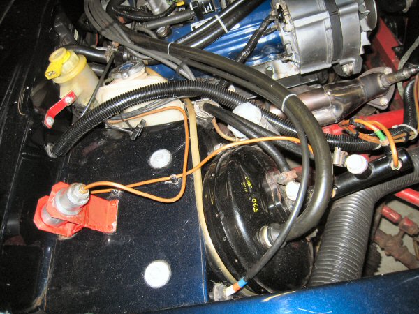
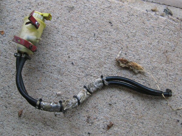
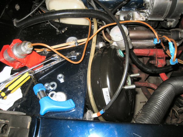
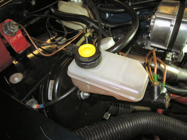
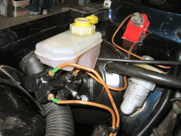
 So this is the completed servo, with the fluid sensor wiring extended and reconnected.
 This second photo, from the front, highlights one thing: the master cylinder is already starting to rust, even although it has never been outside (there's
about 4 weeks between fitting the servo and doing the wiring here).
This second photo, from the front, highlights one thing: the master cylinder is already starting to rust, even although it has never been outside (there's
about 4 weeks between fitting the servo and doing the wiring here).
 I get a wee tin of gloss black paint, and paint the cylinder as best I can, with everything still in place. Important tip, then, if you buy what seems to be
a pattern part: paint it before you put it on!
I get a wee tin of gloss black paint, and paint the cylinder as best I can, with everything still in place. Important tip, then, if you buy what seems to be
a pattern part: paint it before you put it on!
So that's it: a modernised and safer brake system fully installed!